NAND Gates
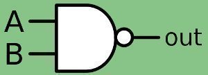
NAND gates are basic logic gates that are used in a number of electronic circuits. An electrician can use a NAND gate to build any other logic gate when it is used with a NOR gate. Therefore, it is sometimes referred to as a universal gate. The most common NAND gate is a two-input gate, which can be created and used with more inputs. NAND gates can be incorporated into a large, integrated circuit and a discrete circuit. A standard microprocessor chip contains several million NAND gates, which will output a logical high unless they receive both inputs, which are logical highs that result in a logical low output.
How to Test a NAND Gate
Step 1 – Identify the VOH, VOL, VIH, and VIL levels for the NAND gate that is used in the circuit. These values are the input and output voltages that indicate the gate’s logical low and high signals. The required supply voltages for the gate are listed in the gate specification and should be noted (the Vdd and Vgnd annotations list them).
Step 2 – Enter the programmable voltage supply to the Vdd level noted in step 1.
Step 3 – Connect the power supply’s positive lead to the pin correlating with the Vdd input on the NAND gate. The negative lead should be connected to the ground or the gate’s Vss pin.
Step 4 – Set the second programmable voltage supply to the VIL setting and connect this supply’s ground to the lead ground of the gate’s first supply.
Step 5 – Configure the third supply to the VIH setting. This supply’s ground lead should then be connected to the first voltage supply’s ground lead.
Step 6 – Connect the VIL power supply’s positive lead to both inputs of the NAND gate. Use a voltmeter to measure the voltage between the NAND gate output and ground. This measurement should be higher than the VOH specification.
Step 7 – Connect the VIH power supply’s positive lead to both inputs of the NAND gate. The measured voltage is lower than the VOL stated specification.
Step 8 – Finally, take the VIH power supply’s positive lead and connect it to the NAND gate’s single input, and connect the VIL power supply’s positive connection to the other input. The voltage at the NAND gate output will be lower than the VOH. Reverse the inputs and the output will remain below VOH.


Comments - One Response to “NAND Gates”
Sorry but comments are closed at this time.